1.7: Protocol Layers and Their Service Models
|
From our discussion thus far, it is apparent that the Internet is an extremely complicated system. We have seen that there are many pieces to the Internet: numerous applications and protocols, various types of end systems and connections between end systems, routers, and various types of link-level media. Given this enormous complexity, is there any hope of organizing network architecture, or at least our discussion of network architecture? Fortunately, the answers to both questions is yes.
1.7.1: Layered ArchitectureBefore attempting to organize our thoughts on Internet architecture, let's look for a human analogy. Actually, we deal with complex systems all the time in our everyday life. Imagine if someone asked you to describe, for example, the airline system. How would you find the structure to describe this complex system that has ticketing agents, baggage checkers, gate personnel, pilots, airplanes, air traffic control, and a worldwide system for routing airplanes? One way to describe this system might be to describe the series of actions you take (or others take for you) when you fly on an airline. You purchase your ticket, check your bags, go to the gate, and eventually get loaded onto the plane. The plane takes off and is routed to its destination. After your plane lands, you de-plane at the gate and claim your bags. If the trip was bad, you complain about the flight to the ticket agent (getting nothing for your effort). This scenario is shown in Figure 1.21.
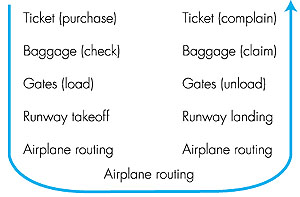 Figure 1.21: Taking an airplane trip: Actions Already, we can see some analogies here with computer networking: You are being shipped from source to destination by the airline; a packet is shipped from source host to destination host in the Internet. But this is not quite the analogy we are after. We are looking for some structure in Figure 1.21. Looking at Figure 1.21, we note that there is a ticketing function at each end; there is also a baggage function for already-ticketed passengers, and a gate function for already-ticketed and already-baggage-checked passengers. For passengers who have made it through the gate (that is, passengers who are already ticketed, baggage-checked, and through the gate), there is a takeoff and landing function, and while in flight, there is an airplane routing function. This suggests that we can look at the functionality in Figure 1.21 in a horizontal manner, as shown in Figure 1.22.
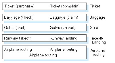 Figure 1.22: Horizontal layering of airline functionality Figure 1.22 has divided the airline functionality into layers, providing a framework in which we can discuss airline travel. Now, when we want to describe a part of airline travel, we can talk about a specific, well-defined component of airline travel. For example, when we discuss gate functionality, we know we are discussing functionality that sits "below" baggage handling, and "above" takeoff and landing. We note that each layer, combined with the layers below it, implement some functionality, some service. At the ticketing layer and below, airline-counter-to-airline-counter transfer of a person is accomplished. At the baggage layer and below, baggage-check-to-baggage-claim transfer of a person and bags is accomplished. Note that the baggage layer provides this service only to an already-ticketed person. At the gate layer, departure-gate-to-arrival-gate transfer of a person and bags is accomplished. At the takeoff/landing layer, runway-to-runway transfer of people and their bags is accomplished. Each layer provides its service by (1) performing certain actions within that layer (for example, at the gate layer, loading and unloading people from an airplane) and by (2) using the services of the layer directly below it (for example, in the gate layer, using the runway-to-runway passenger transfer service of the takeoff/landing layer). As noted above, a layered architecture allows us to discuss a well-defined, specific part of a large and complex system. This simplification itself is of considerable value. When a system has a layered structure it is also much easier to change the implementation of the service provided by the layer. As long as the layer provides the same service to the layer above it, and uses the same services from the layer below it, the remainder of the system remains unchanged when a layer's implementation is changed. (Note that changing the implementation of a service is very different from changing the service itself!) For example, if the gate functions were changed (for example, to have people board and disembark by height), the remainder of the airline system would remain unchanged since the gate layer still provides the same function (loading and unloading people); it simply implements that function in a different manner after the change. For large and complex systems that are constantly being updated, the ability to change the implementation of a service without affecting other components of the system is another important advantage of layering. But enough with airlines. Let's now turn our attention to network protocols. To reduce design complexity, network designers organize protocols--and the network hardware and software that implements the protocols--in layers. With a layered protocol architecture, each protocol belongs to one of the layers. It's important to realize that a protocol in layer n is distributed among the network entities (including end systems and packet switches) that implement that protocol, just as the functions in our layered airline architecture were distributed between the departing and arriving airports. In other words, there's a piece of layer n in each of the network entities. These pieces communicate with each other by exchanging layer-n messages. These messages are called layer-n protocol data units, or more commonly n-PDUs. The contents and format of an n-PDU, as well as the manner in which the n-PDUs are exchanged among the network elements, are defined by a layer-n protocol. When taken together, the protocols of the various layers are called the protocol stack. When layer n of Host A sends an n-PDU to layer n of Host B, layer n of Host A passes the n-PDU to layer n-1 and then lets layer n-1 deliver the n-PDU to layer n of B; thus layer n is said to rely on layer n-1 to deliver its n-PDU to the destination. A key concept is that of the service model of a layer. Layer n-1 is said to offer services to layer n. For example, layer n-1 might guarantee that the n-PDU will arrive without error at layer n in the destination within one second, or it might only guarantee that the n-PDU will eventually arrive at the destination without any assurances about error. Protocol Layering The concept of protocol layering is fairly abstract and is sometimes difficult to grasp at first. This concept will become clear as we study the Internet layers and their constituent protocols in greater detail. But let us now try to shed some insight on protocol layering and protocol stacks with an example. Consider a network that organizes its communication protocols in four layers. Because there are four layers, there are four types of PDUs: 1-PDUs, 2-PDUs, 3-PDUs, and 4-PDUs. As shown in Figure 1.23, the application, operating at the highest layer, layer 4, creates a message, M. Any message created at this highest layer is a 4-PDU. The message M itself may consist of many different fields (in much the same way as a structure or record in a programming language may contain different fields); it is up to the application to define and interpret the fields in the message. The fields might contain the name of the sender, a code indicating the type of the message, and some additional data.
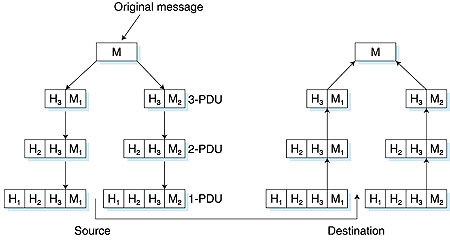 Figure 1.23: Different PDUs at different layers in the protocol architecture Within the source host, the contents of the entire message M is then "passed" down the protocol stack to layer 3. In the example in Figure 1.23, layer 3 in the source host divides a 4-PDU, M, into two parts, M1 and M2. The layer 3 in the source host then adds to M1 and M2 so-called headers to create two layer-3 PDUs. Headers contain the additional information needed by the sending and receiving sides of layer 3 to implement the service that layer 3 provides to layer 4. The procedure continues in the source, adding more header at each layer, until the 1-PDUs are created. The 1-PDUs are sent out of the source host onto a physical link. At the other end, the destination host receives 1-PDUs and directs them up the protocol stack. At each layer, the corresponding header is removed. Finally, M is reassembled from M1 and M2 and then passed on to the application. Note that in Figure 1.23, layer n uses the services of layer n-1. For example, once layer 4 creates the message M, it passes the message down to layer 3 and relies on layer 3 to deliver the message to layer 4 at the destination. Interestingly enough, this notion of relying on lower-layer services is prevalent in many other forms of communication. For example, consider ordinary postal mail. When you write a letter, you include envelope information such as the destination address and the return address with the letter. The letter, along with the address information, can be considered a PDU at the highest layer of the protocol stack. You then drop the PDU in a mailbox. At this point, the letter is out of your hands. The postal service may then add some of its own internal information onto your letter, essentially adding a header to your letter. For example, in the United States a barcode is often printed on your letter. Once you drop your envelope into a mailbox, you rely on the services of the postal service to deliver the letter to the correct destination in a timely manner. For example, you don't worry about whether a postal truck will break down while carrying the letter. Instead the postal service takes care of this, presumably with well-defined plans to recover from such failures. Furthermore, within the postal service itself there are layers, and the protocols at one layer rely on and use the services of the layer below. In order for one layer to interoperate with the layer below it, the interfaces between the two layers must be precisely defined. Standards bodies define precisely the interfaces between adjacent layers (for example, the format of the PDUs passed between the layers) and permit the developers of networking software and hardware to implement the interior of the layers as they please. Therefore, if a new and improved implementation of a layer is released, the new implementation can replace the old implementation and, in theory, the layers will continue to interoperate. Layer Functions In a computer network, each layer may perform one or more of the following generic set of tasks:
Protocol layering has conceptual and structural advantages. We mention, however, that some researchers and networking engineers are vehemently opposed to layering [Wakeman 1992]. One potential drawback of layering is that one layer may duplicate lower-layer functionality. For example, many protocol stacks provide error recovery on both a link basis and an end-to-end basis. A second potential drawback is that functionality at one layer may need information (for example, a timestamp value) that is present only in another layer; this violates the goal of separation of layers.
1.7.2: The Internet Protocol StackThe Internet stack consists of five layers: the physical, data link, network, transport, and application layers. Rather than use the cumbersome terminology n-PDU for each of the five layers, we instead give special names to the PDUs in four of the five layers: frame, datagram, segment, and message. We don't name a data unit for the physical layer, as no name is commonly used at this layer. The Internet stack and the corresponding PDU names are illustrated in Figure 1.24.
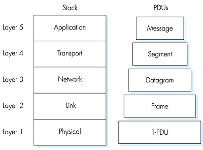 Figure 1.24: The Internet protocol stack, and protocol data units A protocol layer can be implemented in software, in hardware, or using a combination of the two. Application-layer protocols--such as HTTP and SMTP--are almost always implemented in software in the end systems; so are transport-layer protocols. Because the physical layer and data link layers are responsible for handling communication over a specific link, they are typically implemented in a network interface card (for example, Ethernet or ATM interface cards) associated with a given link. The network layer is often a mixed implementation of hardware and software. We now summarize the Internet layers and the services they provide: Application Layer The application layer is responsible for supporting network applications. The application layer includes many protocols, including HTTP to support the Web, SMTP to support electronic mail, and FTP to support file transfer. We shall see in Chapter 2 that it is very easy to create our own new application-layer protocols. Transport Layer The transport layer provides the service of transporting application-layer messages between the client and server sides of an application. In the Internet there are two transport protocols, TCP and UDP, either of which can transport application-layer messages. TCP provides a connection-oriented service to its applications. This service includes guaranteed delivery of application-layer messages to the destination and flow control (that is, sender/receiver speed matching). TCP also segments long messages into shorter segments and provides a congestion control mechanism, so that a source throttles its transmission rate when the network is congested. The UDP protocol provides its applications a connectionless service, which (as we saw in Section 1.3) is very much a no-frills service. Network Layer The network layer is responsible for routing datagrams from one host to another. The Internet's network layer has two principle components. It has a protocol that defines the fields in the IP datagram as well as how the end systems and routers act on these fields. This protocol is the celebrated IP protocol. There is only one IP protocol, and all Internet components that have a network layer must run the IP protocol. The Internet's network layer also contains routing protocols that determine the routes that datagrams take between sources and destinations. The Internet has many routing protocols. As we saw in Section 1.4, the Internet is a network of networks, and within a network, the network administrator can run any routing protocol desired. Although the network layer contains both the IP protocol and numerous routing protocols, it is often simply referred to as the IP layer, reflecting the fact that IP is the glue that binds the Internet together. The Internet transport layer protocols (TCP and UDP) in a source host passes a transport-layer segment and a destination address to the IP layer, just as you give the postal service a letter with a destination address. The IP layer then provides the service of routing the segment to its destination. When the packet arrives at the destination, IP passes the segment to the transport layer within the destination. Link Layer The network layer routes a packet through a series of packet switches (called routers, in the Internet) between the source and destination. To move a packet from one node (host or packet switch) to the next node in the route, the network layer must rely on the services of the link layer. In particular, at each node IP passes the datagram to the link layer, which delivers the datagram to the next node along the route. At this next node, the link layer passes the IP datagram to the network layer. The process is analogous to the postal worker at a mailing center who puts a letter into a plane that will deliver the letter to the next postal center along the route. The services provided at the link layer depend on the specific link-layer protocol that is employed over the link. For example, some protocols provide reliable delivery on a link basis, that is, from transmitting node, over one link, to receiving node. Note that this reliable delivery service is different from the reliable delivery service of TCP, which provides reliable delivery from one end system to another. Examples of link layers include Ethernet and PPP; in some contexts, ATM and frame relay can be considered link layers. As datagrams typically need to traverse several links to travel from source to destination, a datagram may be handled by different link-layer protocols at different links along its route. For example, a datagram may be handled by Ethernet on one link and then PPP on the next link. IP will receive a different service from each of the different link-layer protocols. Physical Layer While the job of the link layer is to move entire frames from one network element to an adjacent network element, the job of the physical layer is to move the individual bits within the frame from one node to the next. The protocols in this layer are again link dependent, and further depend on the actual transmission medium of the link (for example, twisted-pair copper wire, single-mode fiber optics). For example, Ethernet has many physical layer protocols: one for twisted-pair copper wire, another for coaxial cable, another for fiber, and so on. In each case, a bit is moved across the link in a different way. If you examine the Table of Contents, you will see that we have roughly organized this book using the layers of the Internet protocol stack. We take a top-down approach, first covering the application layer and then preceding downwards.
1.7.3: Network Entities and LayersThe most important network entities are end systems and packet switches. As we discuss later in this book, there are two types of packet switches: routers and bridges. We presented an overview of routers in the earlier sections. Bridges will be discussed in detail in Chapter 5 whereas routers will be covered in more detail in Chapter 4. Similar to end systems, routers and bridges organize the networking hardware and software into layers. But routers and bridges do not implement all of the layers in the protocol stack; they typically implement only the bottom layers. As shown in Figure 1.25, bridges implement layers 1 and 2; routers implement layers 1 through 3. This means, for example, that Internet routers are capable of implementing the IP protocol (a layer 3 protocol), while bridges are not. We will see later that while bridges do not recognize IP addresses, they are capable of recognizing layer 2 addresses, such as Ethernet addresses. Note that hosts implement all five layers; this is consistent with the view that the Internet architecture puts much of its complexity at the "edges" of the network.
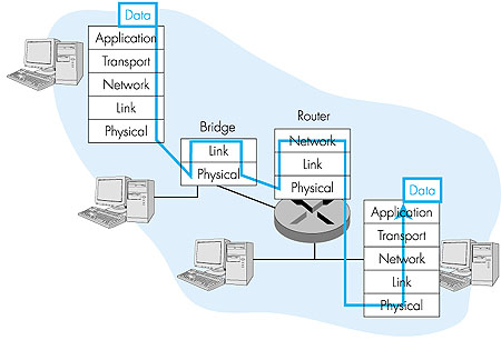 Figure 1.25: Hosts, routers, and bridges; each contains a different set of layers, reflecting their differences in functionality |